The Service dialog is used to define what data to generate, how to generate data values, and where to send the generated data. The Service configuration can only be modified when the Service is inactive. The Add Service dialog is show in Figure 3. Details are provided below.
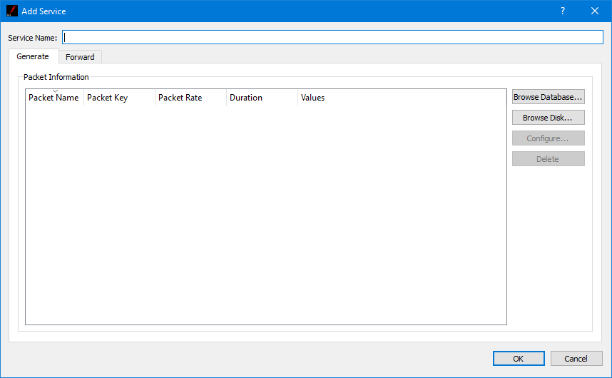
Service Name
Each Service must have a unique name.
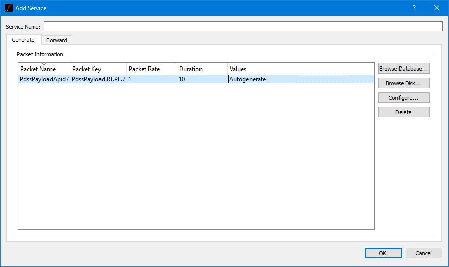
Service Dialog (Generate Tab)
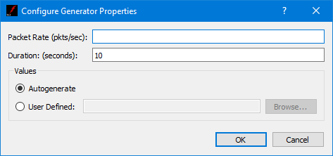
The Service Dialog Generate tab is shown in Figure 4. The Generate tab is used to enter metadata information for each packet to be generated. You can select metadata definitions from a TReK database or browse the disk for metadata files. You can generate one or more packets. Once you have identified a packet to generate you can use Configure to specify how the data should be generated. The Delete button can be used to delete a metadata definition from the list. Figure 5 shows the PdssPayloadApid7 metadata definition in the Packet Information List. To configure the generation of this packet, select the metadata definition in the list and push the Configure button. The Configure dialog shown in Figure 6 will be displayed. This dialog provides the capability to set the packet rate, the duration, and the option to auto-generate the packet data values or use rules defined in a user defined generator file. You can use the Browse button to select a user defined generator file. Information on defining a generator file can be found in Generator File Format. An example generator file is provided in Generator File Example. When you select to auto-generate a data file, the autogen file will be created and placed in the TReK Workspace/generator_file directory. The file will be named autogen_<packet key> (e.g. autogen_PdssPayload.RT.PL.7).
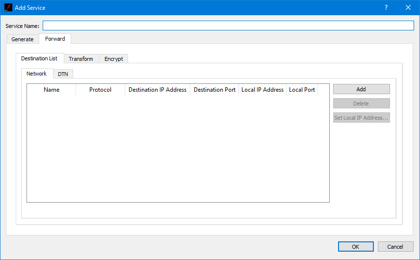
Service Dialog (Forward Tab)
The Service Dialog Forward tab is shown in Figure 7. The Forward tab is used to configure the service to forward generated data.
Each field is described below.
Destination List Tab
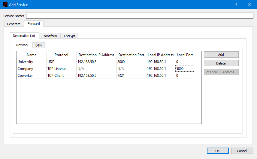
The destination list is used to identify the list of destinations to which the data should be forwarded. Data can be forwarded to a network destination or a Delay Tolerant Network (DTN) destination.
A network destination example is shown in Figure 8. For a network destination, each destination must include a user defined name that is unique in this destination list, a Protocol, and the applicable settings required for the protocol selected. The Protocols supported are UDP and TCP. The Protocol menu provides the capability to select the type of socket to use when forwarding the data: UDP, TCP Client, or TCP Listener socket. Figure 8 shows three different destinations in the Destination List. When using a TCP Listener socket it is not necessary to define a Destination IP Address or a Destination Port. When the Local Port is set to 0, the operating system will automatically select a port to use for the socket that is created to send data to the destination. This is the default as it saves you the trouble of keeping up with ports. However, you can enter a specific port if you would like. This is advisable if you are using a TCP Listener socket since another party will be connecting to the socket. The Add and Delete buttons are used to add a row to the list and delete a row from the list respectively. The Set Local IP Address button can be used to browse for a local IP address and set the value in selected Local IP Address cells.
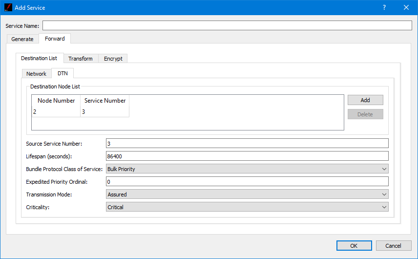
A DTN destination example is shown in Figure 9. For a DTN destination, each destination must include a destination node number and a destination service number. General properties that must be input for all DTN destinations include Source Service Number, Lifespan, Bundle Protocol Class of Service, Expedited Priority Ordinal, Transmission Mode, and Criticality. Each field is described below.
Source Service Number
The source service number is ION’s configured BP service number. This number is used to receive packets from ION.
Lifespan
The lifespan is the bundle's "time to live" (TTL) in seconds. The bundle is destroyed if its TTL has expired and it has not reached its destination. Minimum value is 1, maximum value is 2,147,483,647 and the default value is 86400.
Bundle Protocol Class of Service
The BP class of service defines the transmission priority of outbound bundles from three ION priority queues corresponding to Bulk Priority, Standard Priority, and Expedited Priority. The expedited priority queue must be empty before bundles in the standard or bulk queues are serviced by ION. Therefore, bundles with Expedited Priority should only be sent in critical/emergency situations. The default value is Standard Priority.
Expedited Priority Ordinal
The expedited priority ordinal is only associated with the Expedited Priority class of service. Ordinal values range from 0 (lowest priority) to 254 (highest priority). The default value is 0.
Transmission Mode
The transmission mode defines the reliability of bundle delivery to a destination. The three transmission mode parameter values are Best Effort, Assured, and Assured with Custody Transfer. Best Effort relies upon the underlying convergence-layer protocol (e.g., Transmission Control Protocol or TCP) to retransmit missing bundles. Assured is a step up in reliability and includes BP support in detecting a lost TCP connection and re-forwarding of bundles assumed aborted by the convergence-layer protocol failure. Assured with Custody Transfer requires the reception, by the sending node, of a custody acceptance or refusal signal (packaged in a bundle) from the receiving node. The default value is Assured.
Criticality
A critical bundle is one that has to reach its destination as soon as is physically possible. For this reason, bundles flagged as critical may not include custody transfer and require an ION configuration with contact graph routing. In some cases, a critical bundle may be sent over multiple routes to ensure delivery to its final destination. Critical bundles are placed in the expedited priority queue and should only be used in emergency situations. The two criticality parameters are Not Critical and Critical. The default value is Not Critical.
Transform Tab
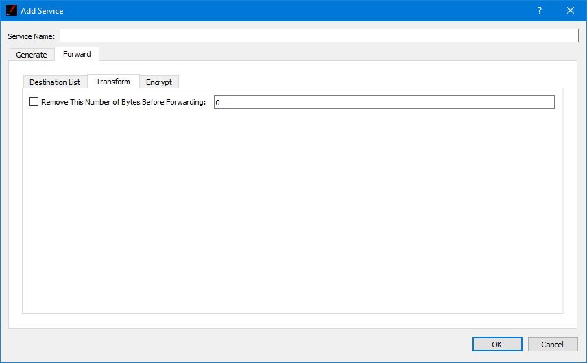
The Transform tab is shown in Figure 10. The Transform tab provides the capability to enable the transform feature which can be used to remove a specific number of bytes from the beginning of each packet before the packet is forwarded.
Encrypt Tab
The Encrypt tab is shown in Figure 11. The Encrypt tab provides the capability to encrypt data sent to a destination. Encryption is controlled per destination.
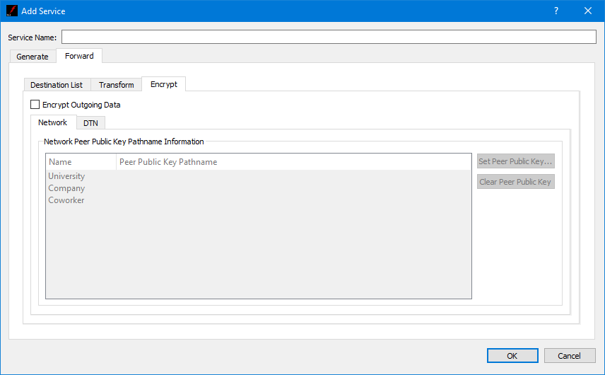
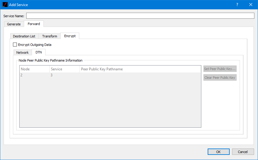
The Peer Public Key Information is populated using the Destination List. To encrypt data going to a specific destination, check the Encrypt Outgoing Data checkbox, and identify the absolute path to the Peer Public Key associated with that destination. The Set Peer Public Key button is used to browse the local disk for a peer public key file. The Clear Peer Public Key button is used to clear a peer public key pathname. One or more rows must be selected to use the Set Peer Public Key and Clear Peer Public Key buttons.